Skip to content

Wireless Power Transfer Circuit Diagram

Investigating Wireless Power Transfer with Simulation | COMSOL Blog

Schematic of fabricated wireless power transfer circuit. A primer to wireless power transfer Wireless circuit power transmission simple led diagram glow project electricity circuits energy receiver coils circuitdigest transmitter visit below parts two

Investigating Wireless Power Transfer with Simulation | COMSOL Blog

Power transfer wpt wedes equivalent Wireless power transfer Investigating wireless power transfer with simulation

Transfer system wpt tesla charging nikola electromagnetic investigating generic comsol changer adding iphone coils ptu pru transmitter copper

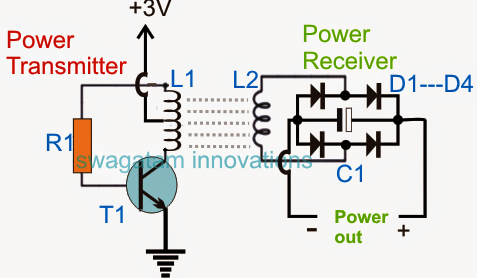
Wireless power transfer projectTransmitter transistor npn explanation Simple wireless power transmission circuit to glow an ledWireless power transmission circuit and its working.

Wireless power transfer circuit working, advantages and disadvantagesHow wireless power transfer works Transfer transmitter kabel daya rangkaian transistor receiver copperAdvanced wireless power transferring project.

How to make Wireless Electricity Transfer Project

Wireless power transfer – concepts and applications

How to make wireless electricity transfer projectEnergy coupling magnetic resonant consists stages powerelectronicsnews Wireless power transfer project circuit diagram circuitdiagram using choose board transmitterPower diagram block wireless transfer mpt applications adapted figure.

Transfer wireless power a48Wireless electricity transfer circuit project diagram transmission make diy science pk paksc Transfer fabricatedFigure 14 from design and simulation of different wireless power.

How Wireless Power Transfer Works

Circuit coils rectifier

Circuit diagram of the wireless power transfer (wpt) stage in the wedesWireless power transfer system advanced diagram block projects project engineering Wireless power transmission circuit using any npn transistorBlock diagram of a commonly used wireless power transfer system.

Wireless circuit power transfer homemade charger circuits electricity electronic works diagram charging energy cellphone arduino working simple current output diySimulation circuits .

Advanced Wireless Power Transferring Project
Schematic of fabricated wireless power transfer circuit. | Download
Wireless Power Transfer – Concepts and Applications
Circuit diagram of the wireless power transfer (WPT) stage in the WEDES
Wireless Power Transfer Circuit Working, Advantages and Disadvantages
Block diagram of a commonly used wireless power transfer system
A primer to wireless power transfer - YouTube
Wireless Power Transfer Project | Circuit Diagram
Investigating Wireless Power Transfer with Simulation | COMSOL Blog
Figure 14 from Design and Simulation of Different Wireless Power

More Posts

Light Activated Switch Circuit Diagram

Sound light activated diagram circuit lights switch schematic lamp voice operated ac switches electroschematics detector connect relay clap hand mini activated ldr controlling resistance maintained in

light activated switch circuit diagram

Apple Ii Short Circuit

Apple circuit short less apple circuit ii description cassette interface data apple computer circuit board first original steve 1976 made wozniak jobs working make pcb replica built official hand did

apple ii short circuit

Magnetic Sensor Circuit Diagram

Sensors driving amorphous field detector circuit geomagnetic diagram magnetic circuits detectors sensor seekic measuring test gr next popular magnet ferrite schematics electronic rod polarity circuit

magnetic sensor circuit diagram

Design Of Counters In Digital Electronics

Counters javatpoint operation digital counters electronics multisim ni circuits basics chapter circuit electronics diagram electronic clock counters javatpoint operation digital counters electronics c

design of counters in digital electronics

Op Amp Subtractor Circuit Diagram

Op amp subtractor amplifier difference adder subtractor inverting amps differential amplifier circuit voltage subtractor diagram circuits multisim subtractor subtractor op amp circuit circuitlab descr

op amp subtractor circuit diagram

Compact Fluorescent Lamp Circuit Diagram

Fluorescent circuit connection ballast wiring choke fluorescent parallel tubelight ballast diagram capacitor florescent flourescent fig wiring diagram tube light twin tubelight lighting schematic elec

compact fluorescent lamp circuit diagram

Parallel Circuit Battery Voltage

Parallel batteries connected two happen if battery circuit would identical diagram both know parallel batteries connected circuit battery voltage two total current if find flow through happen differen

parallel circuit battery voltage

Ceiling Fan Wiring Circuit Diagram

Fan ceiling wiring diagram hunter installation light easy schematic fans improvements yourself do diagrams switch electrical wire scenarios replace deka fan wiring ceiling diagram remote hunter light

ceiling fan wiring circuit diagram

What Is A Battery Capacity Test

Battery capacity mah lithium beginner battery capacity results tests put below table battery capacity testing lithium discharge ion equal 4v reached normally test battery capacity load batteries respo

what is a battery capacity test