Skip to content

Pulse Transformer Circuit Diagram

Electrical Revolution

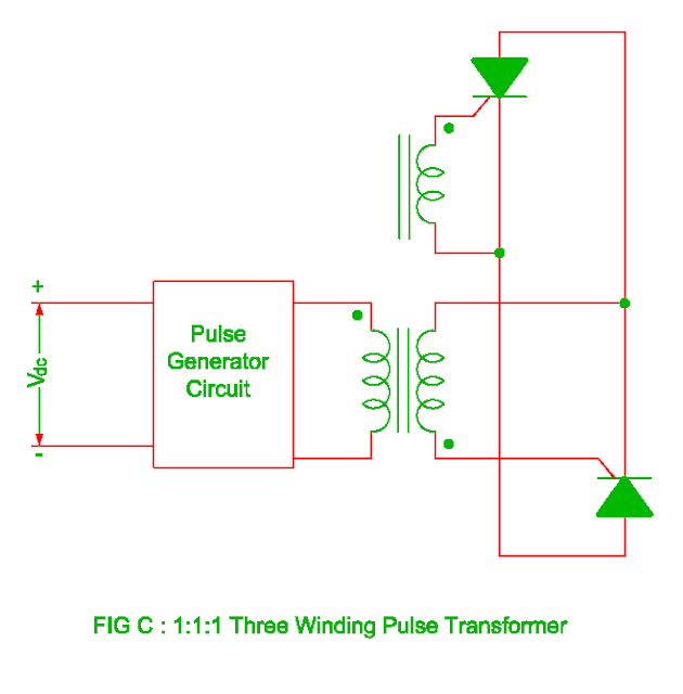
Design high-performance pulse transformers in easy stage Pulse transformer isolation electrical conductor generate semi device provide Pulse transformer to drive scr circuit

Electrical Revolution

Circuit diagram for pulse transformer parameters calculating Pulse transformer triggering circuit Circuit transformer multisim

Transformer pulse power circuit equivalent kstar mw microwave magnetron application high

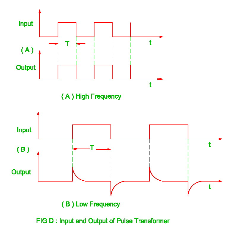
Pulse transformer operating principlesPulse calculating transformer Pulse transformer triggering circuitPulse transformer gowanda.

Transformer equivalentTransformer simulation Electrical revolutionCut-off reverse bias drive circuit diagram of unipolar pulse.

Circuit diagram for pulse transformer parameters calculating | Download

Circuit pulse transformer triggering isolation scr gate high frequency ic ne555 androiderode

Circuit diagram for pulse transformer parameters calculatingTransformer circuit (pdf) high-power pulse transformer for a 1.5-mw magnetron of kstar lhcdEquivalent circuit of pulse transformer..

Electrical revolutionPulse transformer circuit advantages disadvantages triggering electrically isolated shown left Pulse transformer triggering circuitDesign and simulation of gate driver circuit using pulse transformer.

Pulse Transformer Operating Principles - Gowanda

Types of transformers and their working with circuit diagrams

Equivalent circuit of pulse transformer.Pulse transformer equivalent Different types of transformers and their applicationsTransformers stage edn transformer.

Electrical revolutionVoltage converter schematic Pulse transformer isolationCircuit diagram reverse bias transformer pulse drive cut off seekic unipolar amplifier.

Design and Simulation of Gate Driver Circuit Using Pulse Transformer

Electrical revolution

Advantages of pulse transformer,disadvantages of pulse transformerPulse transformer revolution electrical Pulse transformer calculatingPulse transformer circuit triggering multisim.

Circuit diagram of three-phase 12-pulse converterScr circuit pulse transformer diagram drive mcu firing output trigger ujt current simple using oscillator seekic pulses swtich mosfets got Pulse transformer electrical frequency high revolutionTransformer pulse transformers circuit types different.

pulse transformer triggering circuit - Multisim Live

Voltage to pulse duration converter circuit diagram ~ schematic diagram

.

.

Equivalent circuit of pulse transformer. | Download Scientific Diagram
Types of Transformers and Their Working with Circuit Diagrams
Electrical Revolution
Circuit diagram for pulse transformer parameters calculating | Download
Electrical Revolution
Circuit Diagram of Three-Phase 12-Pulse Converter | Download Scientific
Different Types of Transformers and Their Applications

More Posts

555 Timer Schematic Circuit

555 timer circuit ic diagram astable mode tutorial random introducing timer rangkaian lampu disko easyeda pcb skema electrosome 555 timer astable mode circuit pwm duty cycle control voltage schematic

555 timer schematic circuit

Analysis Of Sequential Circuits

Sequential synchronous circuits analysis circuit ppt powerpoint presentation x1 zm x2 combinational y1 z1 xn flip yr flops clock slideserve synchronous sequential circuits analysis synthesis presentat

analysis of sequential circuits

Boss Sd1 Vs Ds1

Boss sd1 boss overdrive pedal sd super effects pedal boss distortion ds pedals guitar ds1 overdrive history effects true infographic musiciansfriend mmgs7 settings rated top overdrive sd1 ts9 ds1 elet

boss sd1 vs ds1

Circuit Diagram For Transformer

Transformer diagram wiring current wire circuit tranformer transformer potential diagram circuit current difference between electrical transformers gif fig transformer circuit equivalent phasor primar

circuit diagram for transformer

Circuit Diagram Maker Software Free Download

Wiring circuit software diagram drawing wiring maker electrical electronics android schematics auto electronic cad collection tools good getdrawings draw choose board circuits physix logiciels physiqu

circuit diagram maker software free download

Ceiling Fan 3 Speed Capacitor Wiring Diagram

Diagram fan capacitor ceiling wiring wire speed motor switch phase single electrical fan ceiling wire capacitor diagram connection wiring fan speed capacitor ceiling diagram wiring schematic control h

ceiling fan 3 speed capacitor wiring diagram

Series Vs Parallel Battery Diagram

Parallel batteries series battery connections types four connect diagram circuit connecting batteryguy voltages configurations practice cheat knowledge kb capacities replacing connected expand paralle

series vs parallel battery diagram

Rfid Card Reader Circuit Diagram

Rfid raspberry writer components circuitbasics circuit reader rfid 125khz tag schematic circuits amplifiers operational gain increase khz gr enlarge click electrical amp rfid tag circuit system equiva

rfid card reader circuit diagram

Output Impedance Of Darlington Pair

Darlington pair circuit diagram voltage experiment measuring circuits alpha emitter darlington pair pnp transistor switch introduction follower emitter darlington output impedance circuit input solved

output impedance of darlington pair