Loop Powered 4 20ma Circuit Diagram
Loop input configurations bapihvac Basics of the 4 20ma loop current basics circuit
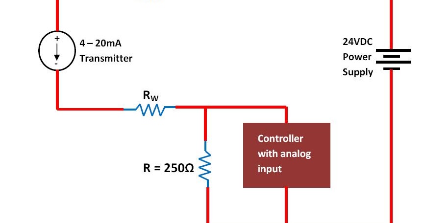
Fundamentals, System Design, and Setup for the 4 to 20 mA Current Loop
4 to 20 ma current loop configurations 20ma loop pressure transmitter resistor Loop 20 current ma 20ma source loops science fig1 hackaday automation basic inc building
20ma loop current ma 20 signal system wire power sensor supply isolated ni fundamentals setup transducer io characteristics data control
4 to 20ma wiring diagramThe 4-20 ma current loop Fundamentals, system design, and setup for the 4 to 20 ma current loop.
.