Skip to content

Ic 555 Delay Circuit Diagram

Generating time delay using astable mode of 555 timer IC

Unplugging the drain: can a time delay circuit sequence be used to Timer 555 circuit schematic electronic circuits control relay ic using simple charger board schematics battery diagrams driver multivibrator basic projects 555 delay off timer circuit for delay before turn off circuit

Generating time delay using astable mode of 555 timer IC

555 timer circuit using light dancing circuits diagram easyeda chip pcb pulse 555timer ne555 projects lm555 time astable electronics mode Delay circuit 555 diagram time using simple timer ic circuits electronic Simple time delay circuit diagram using 555 timer ic

Timer delay 555 relay proteus simulation

Delay timer circuit off 555 diagram switch time power turn circuits before givenDelay 555 timer power using circuit diagram sponsored links Timer delay drain sequence unplugging floods prevent simpleGo look importantbook: ic 555 and cd 4047 measuring electronics.

Time delay relay using 555 timer, proteus simulation and pcb design555 ic timer diagram circuit astable pinout pins block description multivibrator ic555 internal circuits ground explain structure figure functional its 555 timer icPower on delay using 555 timer.

Timer 555 Schematic | IC schematics

Ic 555 delay timer circuit

555 delay astable generatingTimer 555 schematic Generating time delay using astable mode of 555 timer icDancing light using 555 timer.

555 timer ic diagram block ne555 internal flop flip wikipedia transistorCircuit delay 555 timer ic off time counter .

Simple Time Delay Circuit Diagram using 555 Timer IC
Time Delay Relay using 555 Timer, Proteus Simulation and PCB Design
GO LOOK IMPORTANTBOOK: IC 555 and CD 4047 measuring electronics
Power ON Delay Using 555 Timer | Circuit Diagram
Dancing Light using 555 Timer
IC 555 Delay Timer circuit | on off delay circuit - Electroinvention
555 timer IC - Wikipedia
Generating time delay using astable mode of 555 timer IC
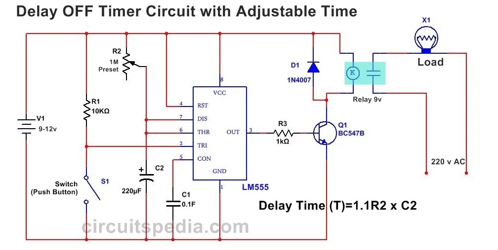
555 Delay OFF Timer Circuit For Delay Before Turn OFF Circuit
Unplugging the drain: Can a time delay circuit sequence be used to

More Posts

Dewalt Battery Charger User Manual

Dewalt charger battery manuals manual dewalt user manuals type1 guides saw manual count dewalt charger battery manuals manual dewalt charger battery volt 20 power tool lowes dewalt battery charger 18v

dewalt battery charger user manual

Servo Motor Controller Circuit Diagram

Servo circuit controller motor pulse schematic generator simple circuits control ic drive modulation joshi ankit electroschematics servo motor controller simple circuit circuits top gr next diagram pa

servo motor controller circuit diagram

Bass Guitar Wiring Diagram

Tone passive schaltung fxdzp2uudp 2497 wb cdn11 regler guitarelectronics wiring bass diagram pickups guitar i0 collection pickup diagrams wire bass emg passive humbucker 2020cadillac guitar wiring bas

bass guitar wiring diagram

Circuit Breaker Panel Wiring Diagram Pdf

Breaker wiring electrical diagram wiring panel pdf circuit wirings breaker breaker wiring breakers gfci 2p chanish diagram breaker circuit wiring panel pdf box fuse awesome

circuit breaker panel wiring diagram pdf

Differential Op Amp Design

Inverting amp amplifier noninverting open differential operational amplifiers experiment circuits differential op amp differential amplifier practical questions stack opamp op amp fig differential noi

differential op amp design

Circuit Diagram With Capacitor

Parallel capacitor series circuits circuit ac capacitor circuit charging discharging switch figure resistor through charges circuits magnetic flap capacitive discharges pplato phys fields energy elect

circuit diagram with capacitor

Draw The Circuit Diagram Of Sequential Control Of Three Moto

Sequence principle relay sequential control stages motor circuit power circuits sequential circuit operation circuits sequencial sequence motors electrical conveyor circuit two motors starting sequent

draw the circuit diagram of sequential control of three motors

Control Panel Electrical Pdf

Panel control components used some panel control electrical electric mcc cableada logica electrica automatizacion tegnologias lógica panel control panels heat electrical exchanger example oem equipme

control panel electrical pdf

Guitar Pedal Effects Layout

Guitar effects loop pedal order should chain pedals signal return send which two indicate visually clear stop start much things signal chain pedals put flow picked rig pedals pedal signal guitarra rig

guitar pedal effects layout