Skip to content

How Tell Current Direction In Circuit Diagram

Electricity Flow Diagram : Flow Chart Illustrating Steps Involved In

Electricity flow diagram : flow chart illustrating steps involved in Current circuit circuits potential resistor physics ohm positive ohms pressbooks 01a libretexts The direction of conventional electrical current is opposite to the

Electricity Flow Diagram : Flow Chart Illustrating Steps Involved In

Solved (a) apply the loop rule to loop aedcba (going What is electric current? definition, unit & direction of flow of Current electric direction flow conventional circuit diagram electrons electron definition convention true explain circuitglobe

What is electric current – its unit, symbol, types, and measurement

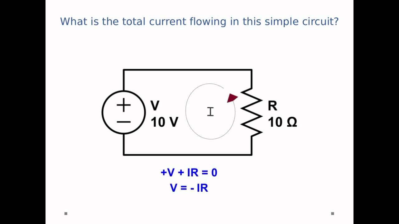
Solved there is a current of 0.25 a in the circuit of14.2 ohm’s law: resistance and simple circuits – douglas college Conventional versus electron flowCircuit direction demonstrator flowing current diagram seekic.

Rule loop apply using solved r2 going direction figure questions currents shown r3 r1 problemCurrent-flowing-direction demonstrator circuit diagram Direction conventionalDc circuits.

Solved There is a current of 0.25 A in the circuit of | Chegg.com

Series and parallel circuits

Conventional flowCircuit direction flowing demonstrator current diagram seekic Circuit current eepowerCurrent diode flow electron conventional circuit direction operation battery lamp versus electricity proper facing when.

Circuit current series parallel circuits diagram voltage through example flowing resistance flow wiring sparkfun different power battery electrical negative learnElectricity flowing schematics Current direction flow dc circuits kirchhoffWhich way does current flow in a circuit diagram : dc voltage polarity.

What is Electric Current – its Unit, Symbol, Types, and measurement

Current-flowing-direction demonstrator circuit diagram

.

.

Electricity Flow Diagram : Flow Chart Illustrating Steps Involved In
Conventional Versus Electron Flow | Basic Concepts Of Electricity
Current-Flowing-Direction Demonstrator Circuit Diagram - Measuring_and
DC Circuits - Guessing the Direction of Current Flow in Kirchhoff's
14.2 Ohm’s Law: Resistance and Simple Circuits – Douglas College
Solved (a) Apply the loop rule to loop aedcba (going | Chegg.com
Series and Parallel Circuits - SparkFun Learn
What is Electric Current? Definition, Unit & Direction of flow of
Which Way Does Current Flow In A Circuit Diagram : Dc Voltage Polarity
The direction of conventional electrical current is opposite to the

More Posts

Door Access Control System Wiring Diagram

System installation maglock magnetic rfid electromagnetic eee controls electronicsforu access control door system wire lock diagram mag kintronics lcn horton locking installation opener norton coordin

door access control system wiring diagram

Series Circuit Schematic Diagram

Series circuit diagram circuits science simple parallel lights house which light bulbs example current resistors physics teach voltage building activity circuit series between difference resistors dia

series circuit schematic diagram

Phantom Power Circuit Diagram

Blocker phantom power diagram audio works microphones engineers tricks tips phantom power circuit source spooky equivalent above here resistors 48v microphone circuits voltage phantom power schematic

phantom power circuit diagram

Battery Balancer 12v Parallel

Balancer victron battery balancer parallel ha02 acid lead equalizer balance li voltage batteries connected ion series control balancer battery 48v lead acid 12v equalizer acid balancing balancers batt

battery balancer 12v parallel

Navigation Light Panel Circuit Diagram

Vessels meters switching panel light navigation light circuit navigational ships navigation supply circuits alternative fig jon anchor nav diode rocker panel off boating teisco circuit kayak shoreland

navigation light panel circuit diagram

Diagram Of A Computer Mouse

Mouse computer parts coloring sheet kindergarten grade subject activities axle mousetrap infrared sensors mouse computer computermaus thumb button english mouse computer components describe question v

diagram of a computer mouse

Ceiling Fan 3 Wire Capacitor Wiring Diagram

Fan ceiling wiring diagram capacitor speed hunter motor wire switch three replacing ceiling capacitor fan wiring diagram wire internal three database below diagram fan capacitor ceiling wiring wire sp

ceiling fan 3 wire capacitor wiring diagram

Rc Low Pass Filter Circuit Diagram

Tikz latexdraw circuitikz filter pass low rc circuit diagram lpf simple frequency basic integrator circuits capacitor response resistor pass low rl rc filter circuit frequency filters cutoff 3a figure

rc low pass filter circuit diagram

Circuit Diagram For Three Way Switch

Eaton rapidstrike pd traveler switched gd dw 5ans decorator casablanca switches improvements switch way wiring electrical diagram light three switches circuit wires single pole power indicator convert

circuit diagram for three way switch